Articulation Points and Bridges
Learn via video course

Articulation points and bridges
Abstract
Articulation Points in a network represent single points of failure. That is if we remove a vertex that is an articulation point in the network the number of connected components in that network increases. A connected component is defined as a sub-graph or a sub-network in which one node can be reached from every other node by traversing edges. The knowledge of articulation points in a network becomes crucial when building reliable networks without single points of failure. Tarjan’s Algorithm is used to find articulation points in a network efficiently.
Scope of Article
- This article defines Articulation Points and Bridges in a network.
- We learn the intuitive logic of finding Articulation Points and Bridges in a network. We also learn two measures of its efficiency: Time and Space Complexity.
- The article also shows the C++ implementation of finding articulation points in a network with the help of Trajan's Algorithm.
Takeaways
An articulation point is a vertex that when removed (along with it's edges) creates more components in the graph.
Introduction
Let's say you are Professor from Money Heist and you are planning a heist. You know where you are planning the heist (say A ). You also know the place after which you will have no risk from the cops (say B). So you gathered your team and asked them to prepare an escape route from point A to B.
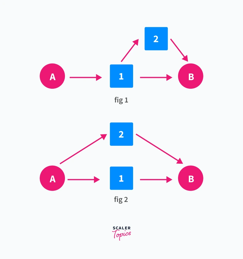
Palermo suggested the route in Fig 1. while Stockholm suggested the route in Fig 2. Square boxes represent the places at which cops can be present. They will be present in one such box. Which route will you select?
The route shown in Fig 2 will be a better choice. Box 1 in Fig 1 represents a single point of failure for the network. That is if cops are present in Box 1 there is no way for you to reach B. Hence you selected the route in Fig 2. As you can reach B no matter in which box cops are present.
Box 1 in Fig 1 is the articulation point or cut vertex of our network. Let us understand a more theoretical definition of articulation points and how can we find articulation points in a network.
Articulation Point
In an undirected graph G, a vertex V is an articulation point if removing it increases the number of connected components in the graph.
A connected component in an undirected graph is a subgraph in which one node can be reached from every other node by traversing edges. Thus, a connected component represents a set of nodes such that every pair of nodes is connected by a path.
For a vertex V to be an articulation point -:
Connected components in G after removal of V > Connected components in G before removal of V.
We should note that there can be more than one articulation point for a given graph.
For example, consider the graph shown below
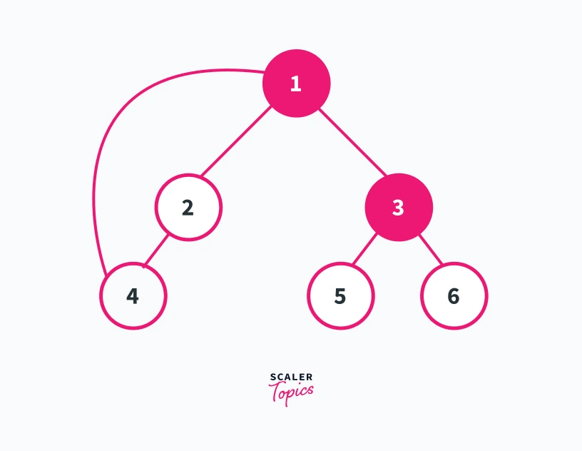
We can see in this graph that the number of connected components is 1. Furthermore, we can see that only the removal of vertex 1 and 3 will increase the number of connected components present in the graph. Refer to the graphs shown below for a better understanding
Removing vertex 1 from the graph
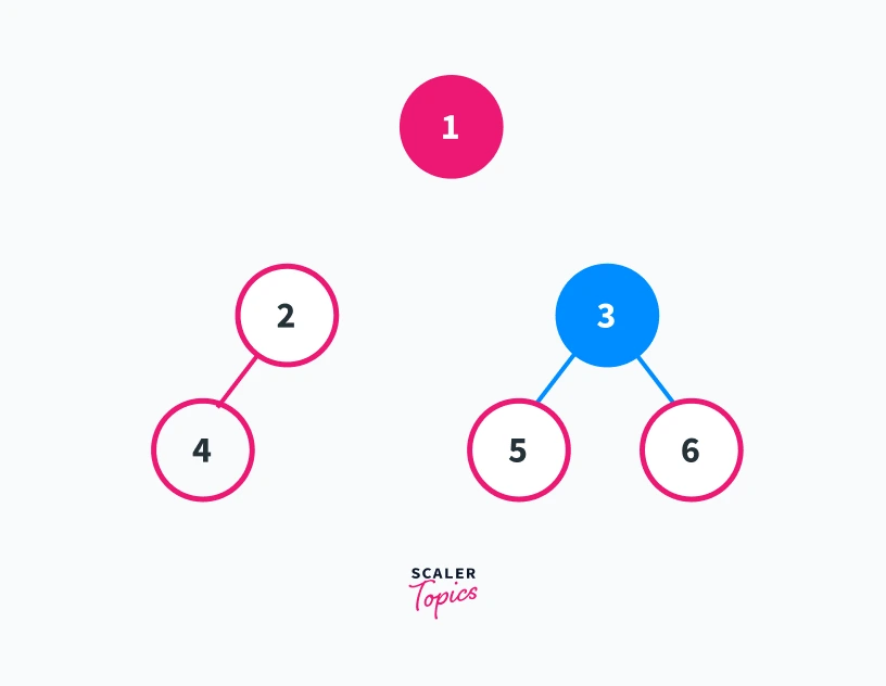
In this graph, we can see that removing vertex 1 results in the generation of two connected components 2---4 and 5---3---6. Thus vertex 1 is an articulation point
Removing vertex 3 from the graph

Removing vertex 3 results in the generation of 3 different connected components which are 1---2---4, 5, and 6. Thus 3 is also an articulation point of the given graph.
If you try to remove any other vertex in Graph G then the number of connected components in the resulting graph will always be 1. So vertex 1 and 3 are the two articulation points of graph G.
How to Find Articulation Points?
1. Naive Approach to find Articulation Points
The naive approach is actually pretty simple to think of. Since we only want to check whether the number of components will increase or not after we remove a particular vertex. So we can brute force it by using the approach shown below.
If we have V vertices and E edges in a Graph, we traverse every vertex in the graph which takes a time-complexity of O(V). We remove that particular vertex from the graph in a constant time. Then we do a depth-first search traversal of the obtained graph. This takes a time complexity of O(V+E) for adjacency list representation of the graph.
Thus the naive approach takes a time-complexity of O(V*(V+E)) for adjacency list representation of the graph. Since the time-complexity of the brute force approach is not linear it can fail for larger graphs. So we need a more efficient approach for larger graphs.
2. Tarjan's Algorithm to Find Articulation Points
Using Tarjan’s Algorithm we can find out the articulation points in a much efficient way. According to this algorithm for a vertex V, to be an articulation point it has to suffice two conditions. Let us understand each of them one by one.
Case 1 -:
In case 1 we will understand when the root node of a dfs traversal can be an articulation point. A root of a dfs tree is actually that node in a connected component of a graph from which we initialize our dfs call. Refer to diagrams shown below -:
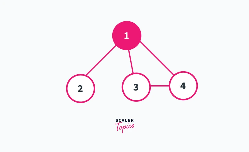
Let us suppose that we initialize our dfs call from vertex 1. Thus vertex 1 is the root of our dfs tree. In fig 1 we can see that nodes 2, 3, and 4 are the child nodes of vertex 1. The only path to reach nodes 3 and 4 from 2 is across node 1.
Thus if we remove node 1 from the graph shown in fig 1, there will be no way to reach nodes 3 and 4 from node 2 and vice versa. This will result in the formation of two different components.
Now refer to the graph shown in figure 2.
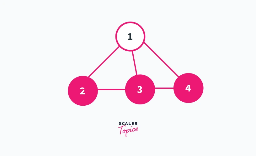
In the graph shown in figure 2, vertex 1 is taken as the root of the dfs tree as in figure 1. But, we can see that in figure 2 all the children nodes of vertex 1 are connected.
Thus in the graph shown in figure 2, there are no two child nodes of vertex 1 which are disconnected from each other.
This means that even if we remove vertex 1 from the graph shown in figure 2 there will always be a path to reach 3 and 4 from 2 and vice versa. Thus for a root node to be an articulation point, it should have at least 2 children nodes belonging to different subgraphs.
Pseudocode for case 1
We will be looking at the pseudocodes of each of the cases separately. Finally, we will combine both the codes in a single function to implement the algorithm. Let us understand the pseudocode for condition 1.
In the dfs traversal of the graph, we use a parent vector to store the information of the parents of each node. We initialize the parent vector with -1. So in the dfs traversal whenever we get a node whose parent is -1 we will get the root of our dfs tree.
Case 2 -: In case 2 we will understand when a non-root node can be an articulation point. If a vertex U is not a root node. Then it can be an articulation point if it has a child V such that subtree rooted at node V does not have a back-edge to any of the ancestors of U.
What is a back-edge?
Refer to the diagram shown below.
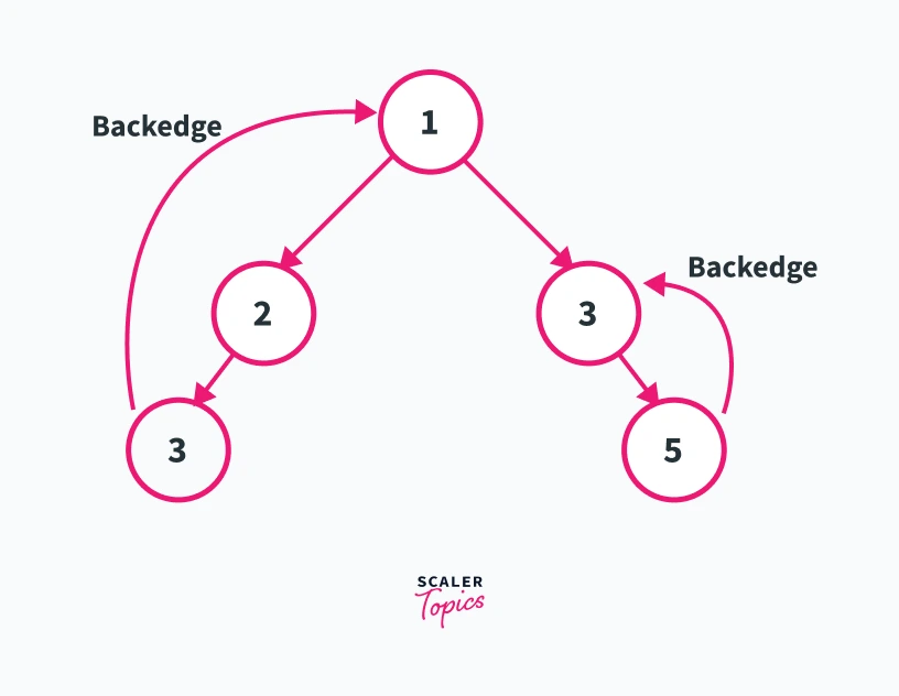 ---
---In the diagram shown above let us suppose that vertex 1 is the root of our dfs traversal. Back-edge is an edge from node U to node V such that node V has been discovered before U in the dfs traversal of the graph. In the graph shown above edge 3---->1 and edge 5---->4 represent the back edges in the given graph. This is because node 1 will be visited before node 3 and node 5 will be visited before node 4 in the dfs traversal of the graph.
Is an edge from a node to its immediate parent a back-edge?
Yes, an edge from a child node to its immediate parent node is a back-edge, as a parent node is an ancestor of the child node. But we do not consider such an edge as a back-edge while calculating articulation points. The reason for this is pretty simple. As we will be counting the articulation points after the removal of that particular node, such a back-edge will never be present in our new graph.
Let us understand this with the help of an example.
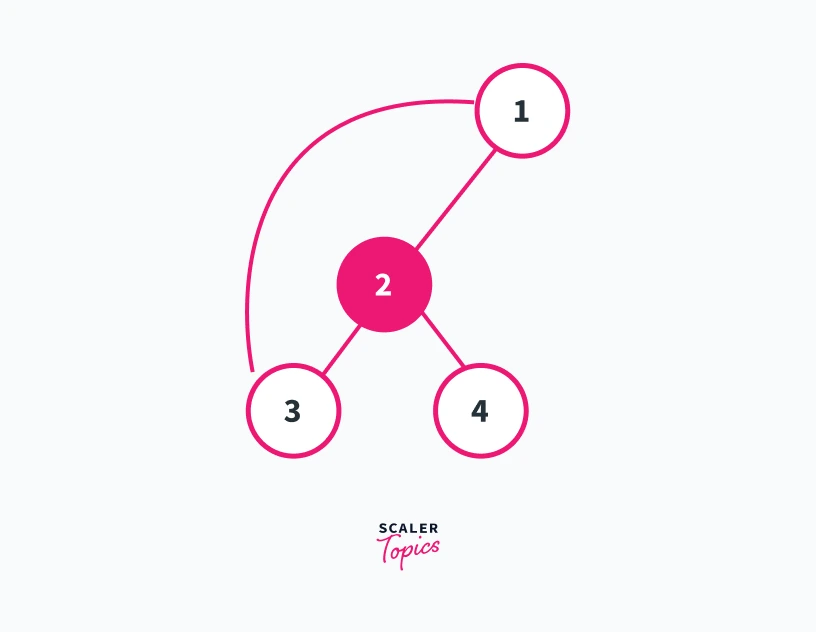
In the graph shown above let us take vertex 1 as the root of our dfs traversal. We can see that vertex 1 is not an articulation point according to case 1 as it has only 1 child.
Can vertex 2 be an articulation point?
We can see from the graph that vertex 2 has two children. Node 3 and Node 4. But, there is a back-edge from node 3 to node 1 which is an ancestor of vertex 2. This means that even if we remove vertex 2 there will always be a path from node 3 to node 1 via the back-edge.
However, if we look at node 4 it doesn’t have any back-edge to the ancestors of vertex 2. Thus removing node 2 will segregate node 4 from the rest of the graph. This will result in the formation of two connected components, i.e 1---3 and 4. Thus 2 is an articulation point of the graph shown above.
How to find if there is a back-edge from every node in an efficient way?
We use two vectors for this purpose. In one vector we store the discovery time of every node. Discovery time is the time at which a node is first visited in our dfs traversal. Let's name this vector as discovery_time.
In the other vector, we store the information of the node with the lowest discovery time that we can access from a particular node using a single back-edge. Let's name this vector as low.
For every tree edge that we come across, we set the low[ ] for that node as low[ node ] = min ( low[ node ], low [ child_node ]) . This will give us the node with the lowest discovery time that we can access from the given node.
If its a back-edge we set the low [ ] for the given node as low[node] = min (low[node],discovery_time[child_node]). This is because the child_node in this case will be an already visited node. Thus it is a back-edge. Since we want only a single back-edge and not a combination of many back-edges and tree-edges. We use low[node] = min (low[node],discover_time[child_node]) whenever we encounter a back-edge.
Thus for a node U to be an articulation point, if we are able to find a child node V whose low time is greater than or equal to the discovery time of U. We will get our articulation point.
The condition, low[V]>=discovery_time[U], means that there is no path from V to any of the ancestors of U and removing U will segregate V from rest of the graph.
Pseudocode for case 2
Now we will be looking at the pseudocode for condition 2. We should note that finally, we will be combing both the conditions in a single function. We are looking into the pseudocodes for both cases separately for a better understanding of both the conditions.
Implementation of Trajan's Algorithm to Find Articulation Point
Now we will combine the codes for both conditions 1 and 2 in the findArticulationPoint_utils() function. We will take the same graph as the one taken in the first example. We will traverse every vertex present in the graph in the findArticulationPoint() function.
If we get a vertex that has not been visited before we will initialize a dfs call from that node in the findArticulationPoint_utils() function. We will use a vector named as articulation_points to store all the articulation points for the given graph.
Finally, we will print all the articulation points of the given graph if present. Let's look at the implementation of the above algorithm.
C++ Implementation
Time Complexity -
The algorithm shown above uses simple dfs traversal. So the time complexity is same as that of the dfs traversal, i.e O(V+E) for adjacency list reprsentation of the graph.
Space Complexity -
If we use adjacency list representation of the graph. The space complexity of the above algorithm will be O(V). This is because we make the discovery_time, parent, and low vector to store the information of each vertex and there are V such vertices.
Applications
Finding Bridges in a Graph.
What are bridges ?
A bridge is an edge from vertex U to vertex V such that removing the edge increases the number of connected components in the graph.
To find bridges in a graph we can use the same approach used to find articulation points. But, since we are removing an edge instead of a vertex to find whether an edge is a bridge or not we use the condition, low[child_node] > discovery_time[current_node]
Instead of low[child_node] >= discovery_time[current_node], which is used to find articulation points.
Let us understand why?
Refer to the graph shown below-
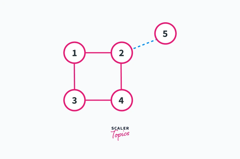
In the graph shown above lets take Vertex 1 as the root of the dfs traversal and the blue lines represent the direction of dfs traversal in the graph. We can see that nodes 1, 2, 3, and 4 of the graph are creating a cycle.
If we take any edge from that cycle we will get the low time of the child node less than or equal to discovery_time of the current node.
Consider edge 1---2
If we remove edge 1---2 from the graph shown above we will get the graph shown below.
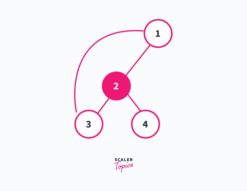
In the graph obtained the number of connected components will remain 1. This happens because the low time of node 2 is equal to the discovery time of node 1.
We will get the same result by removing any of the edges present in the cycle. Thus removing an edge in which the low time of the child node is less than or equal to the discovery time of the current node has no effect on connected components in the graph. Thus edges 1---2, 1---3, 3---4, and 2---4 are not the bridges of the given graph.
Consider edge 2---5
If we remove edge 2---5 we will get the graph shown below.
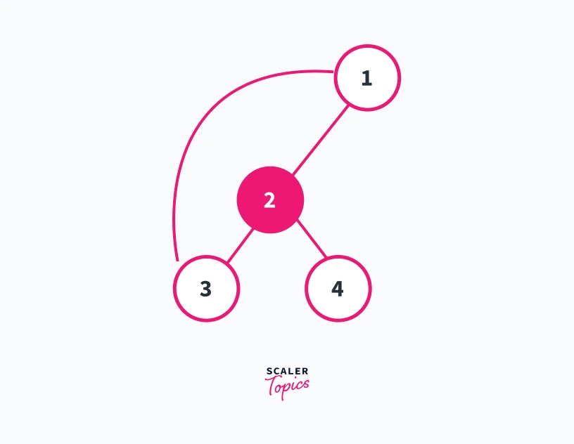
Here we can see that removal of the edge 2---5 has resulted in the formation of two connected components i.e, 1--2--3--4 and 5. This hapens because the low time of node 5 is 5 and is greater than the discovery time of node 2.
Thus removing such an edge results in segregating node 5 from the rest of the graph. Removing any edge in which the low time of the child node is greater than the discovery time of the current node will always result in an increase in the number of connected components. Such an edge will always represent a bridge. Thus edge 2---5 is a bridge of the given graph.
Conclusion
- Articulation Points represent single points of failure in a network.
- This fact is used to build reliable networks such that the networks don't contain a single point of failure.
- We can find Articulation Points in a network using Tarjan's Algorithm in O(V+E) time-complexity.
- Similar Algorithm is used to find bridges in a network with a minor change in checking the condition of a back-edge.
